
BVV-105: E-mail-SMS-Gateway
BVV-105 Is a small, DIN-rail mountable device, which works as a local SMTP-server i.e. e-mail server. This means, that it can receive e-mail messages locally, and relay them as text messages (SMS) through serially connected GSM-modem.
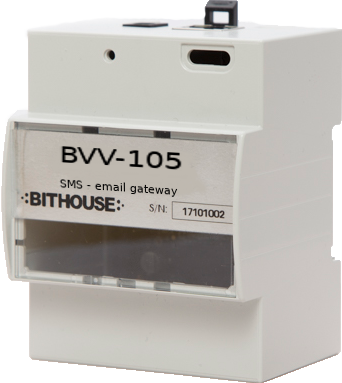
In typical usage, BVV-105 receives email message (usually alarm message) from building automation controller , converts message to SMS message, and sends it to receiver.
Receiver messages can also be relayed to smtp-server, to be delivered as emails.
Configuration and commissioning is performed through web-based user interface.
NOTE! For sending SMS messages to GSM network, BVV-105 needs working GMS-modem like Cinterion BGS2T attached to it. 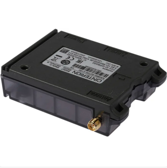
How does it work?
BVV-105 (a.k.a. Viesti-Vertti) works as local MTA (mail transfer agent), also known as email server. It means, that it functions as local SMTP server, then it identifies messages which has numerical local-part (a.k.a mailbox or username) - that is the address part before the '@'-symbol. Then it sends them as text messages (SMS). Messages with regular receiver email address it relays to configured SMTP server, and forwards as regular email messages.
Commissioning steps
Step 1: Connect cables to BVV-105:
- Ethernet cable to connect BVV-105 to same local network with devices generating messages
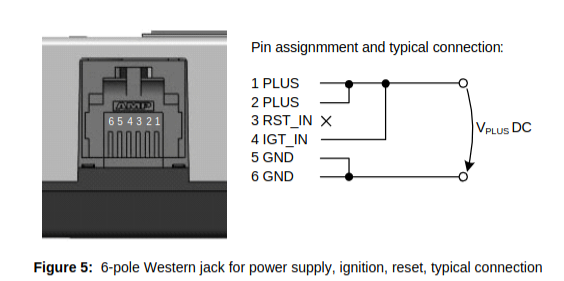
- Power cable for BVV-105. Power connector is 5,5mm x 2,1mm barrel plug +5 V DC with center positive contact.

- Connect USB to RS232-converter cable to BVV-105
Step 2: Connect cables to SMS-modem:
- Connect antenna cable to SMA connector.
- Connect power supply cable. Its usually +9 V DC over RJ11-modular connector.
- Connect serial cable. Connector is DB9 connector (a.k.a. RS232 serial port connector).
Step 3: Power up modem and BVV-105.
- BVV-105 has indicator lights visible through encloruse holes. You can also see blue "heart beat" light blinking from the PCB of device when the operating system is started and running. Correct beat is two quick blinks with longer 750ms pause.
- Green light in GSM modem.
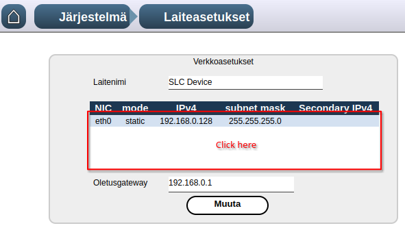
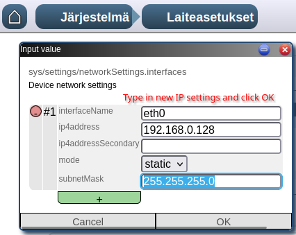
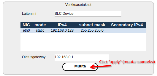
Step 4: Setup IP address
You can access web UI of the BVV-105 with web browser. Default address is http://192.168.0.128.
- Connect your computer with cable to same LAN router with BVV-105.
- Configure your computer to 192.168.0.0/24 network. E.g. set you computers IP address as 192.168.0.129 with network mask 255.255.255.0
- Open web browser, type or copy URL address http://192.168.0.128
- Login to device user interface with username and factory password
- Change factory password from system/user management -page
- If needed, change the IP address from system/settings -page
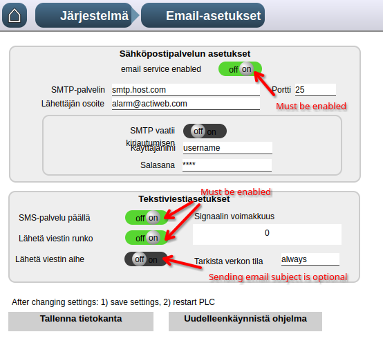
Step 5: Check modem settings
- Check that all needed features are enabled, Then click "save database" then "restart PLC software"

- Check baud rate
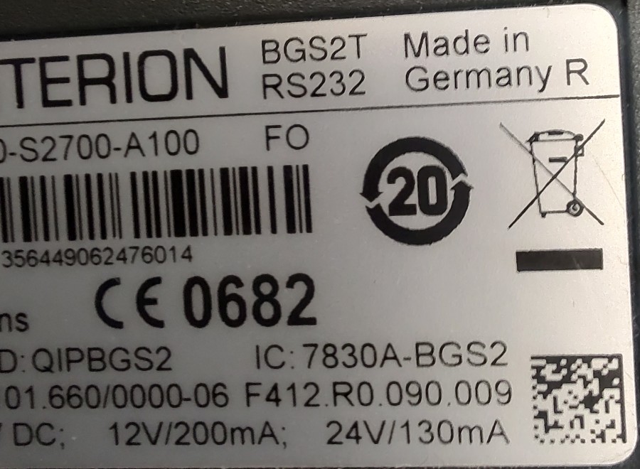
| 2G modem Cinterion BGS2T label, correct baud rate is 9600 | 4G/LTE modem Cinterion EGX81-W, correct baud rate is 115200 |
 |
|
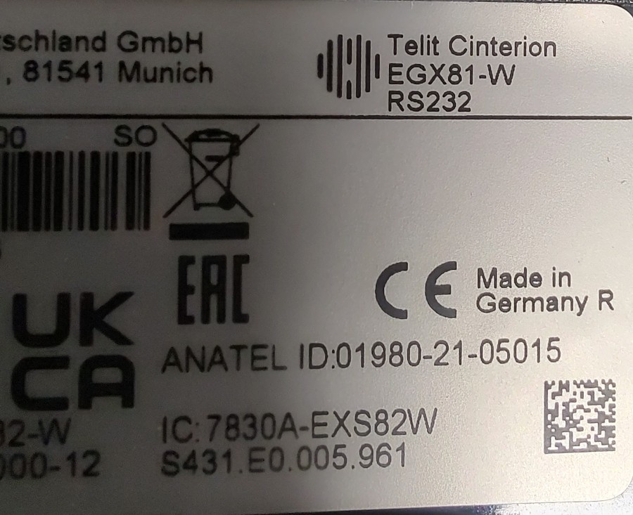
Check from modem documentation, what is the correct baud rate for serial communication. NOTE! In images above you can see correct settings for 2 widely use SMS modem types.
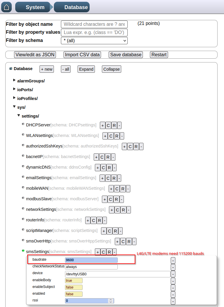
Then, press "save database" and then "restart" buttons
Step 6: Check system status
On home page, you should check the "SMS service log", and there should be row saying "modem is registered to netowork".
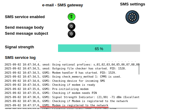
Its also possible, that you see some error messages. They always needs to be resolved - If needed, you can contact the manufacturer.
Device is now ready to send messages.
Cinterion BGS2T
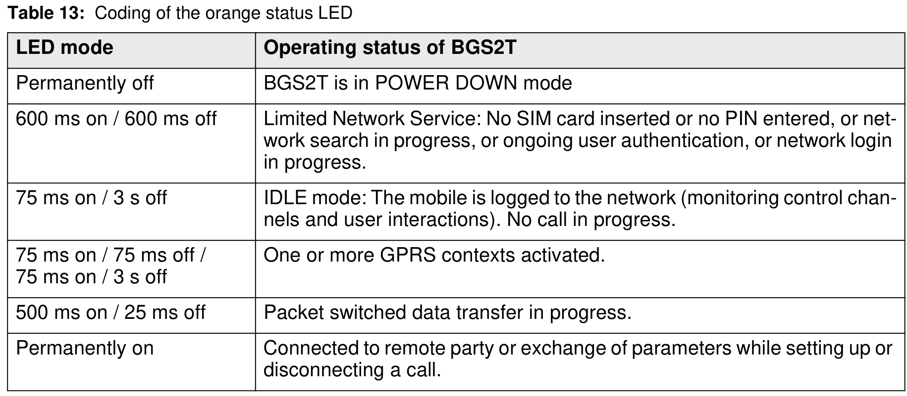
Modem status LED (2G-modem: BGS2T)
The orange status LED of BGS2T can help with troubleshooting: Usually the SIM card (or cellular service subscription) is at fault if the LED is blinking in the Limited Network Service mode (600 ms on/600 ms off). In this case a more specific error code can be read from the SMS Daemon log (a reboot of BVV-105 may be required to show the log at the beginning).
Normally the LED should blink in the IDLE mode (75 ms on/3 s off).
Modem status LED (4G-modem: EGX81-W)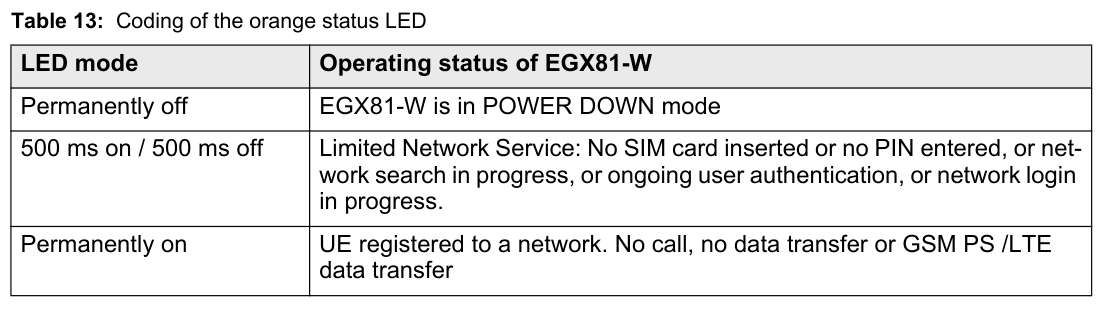
BGS2T manual:
cinterion-bgs2t-man_1-0-0_en.pdf
Power connector pinout:
Wire colors in pig-tail style power cable:
| Johdinväri | Selite |
| Red ▆ , White ▆ |
+8 .. +30V DC |
| Black ▆, Purple ▆ |
Not connected |
| Yellow ▆ , Brown ▆ |
Ground (0 V DC) |
Material
Downloads:
BVV-105 commissioning 2023-02-15.pdf
BVV105-ip-palautus-ohje-2019-11-22.pdf
Technical data |
|
| Electrical |
|
|
Supply voltage |
5 V DC |
|
Supply current |
< 500 mA |
| Connectors |
|
| Ethernet |
1 x 10/100 Mbps |
| USB |
1 |
| MicroSD |
1 (max. 32GB card) |
| Integration |
|
| SMTP server |
|
| Modbus TCP/RTU |
|
| Bacnet/IP |
|
| Mounting |
|
| IP rating |
IP20 |
| Enclosure material |
PC / ABS plastic |
| Op. temperature |
-40 .. 85 °C (< 95% RH) |
| Dimesions |
72 x 91 x 63mm (W x H x D) |
| Weight |
130 g |
No Comments